"How much can one cuplock standard take?" is one of the most common questions we get from contractors planning a shoring tower or a tall access scaffold. The honest answer is: it depends — and what it depends on is worth understanding, because getting it wrong is how scaffolds fail. A standard does not have a single fixed capacity. Its safe working load changes dramatically with how it is set up. This article explains the factors that govern a cuplock standard's load capacity, gives an indicative load-versus-height guide, and shows where an engineered design becomes essential.
It's a Buckling Problem, Not a Crushing Problem
A cuplock standard is a 48.3mm outside-diameter steel tube with a 3.2mm wall, made from EN10219 structural steel. The steel itself is enormously strong in pure compression — far more than any scaffold will ever apply. A standard almost never fails by the steel being crushed. It fails by buckling: the slender tube bows sideways under axial load and loses stability long before the material is overstressed.
That single fact explains everything about scaffold load capacity. Because failure is governed by buckling, the capacity depends not on the tube's cross-section alone but on its effective length — how far the tube can bow between points where it is held in place. Shorten the effective length and the capacity climbs steeply; lengthen it and the capacity drops just as steeply.
The Five Things That Set the Capacity
1. Lift height (the dominant factor). The lift height is the vertical distance between two braced node levels — effectively the unsupported length of the standard. Ledgers and braces locked into the cups at each lift level hold the standard at that point. A 1.0m lift gives a short, stiff column; a 2.0m lift gives a much more slender one. Because buckling capacity falls with the square of effective length, halving the lift height does far more than double the capacity. This is why shoring towers use closely spaced lifts.
2. Bracing. Bracing is what makes the lift height real. Diagonal braces square the structure and stop the node points from translating sideways; without them, the "effective length" can be the full height of the tower, not one lift. Bracing must be installed as each lift is built — never left out or stripped early. See our component guide for the minimum bracing pattern.
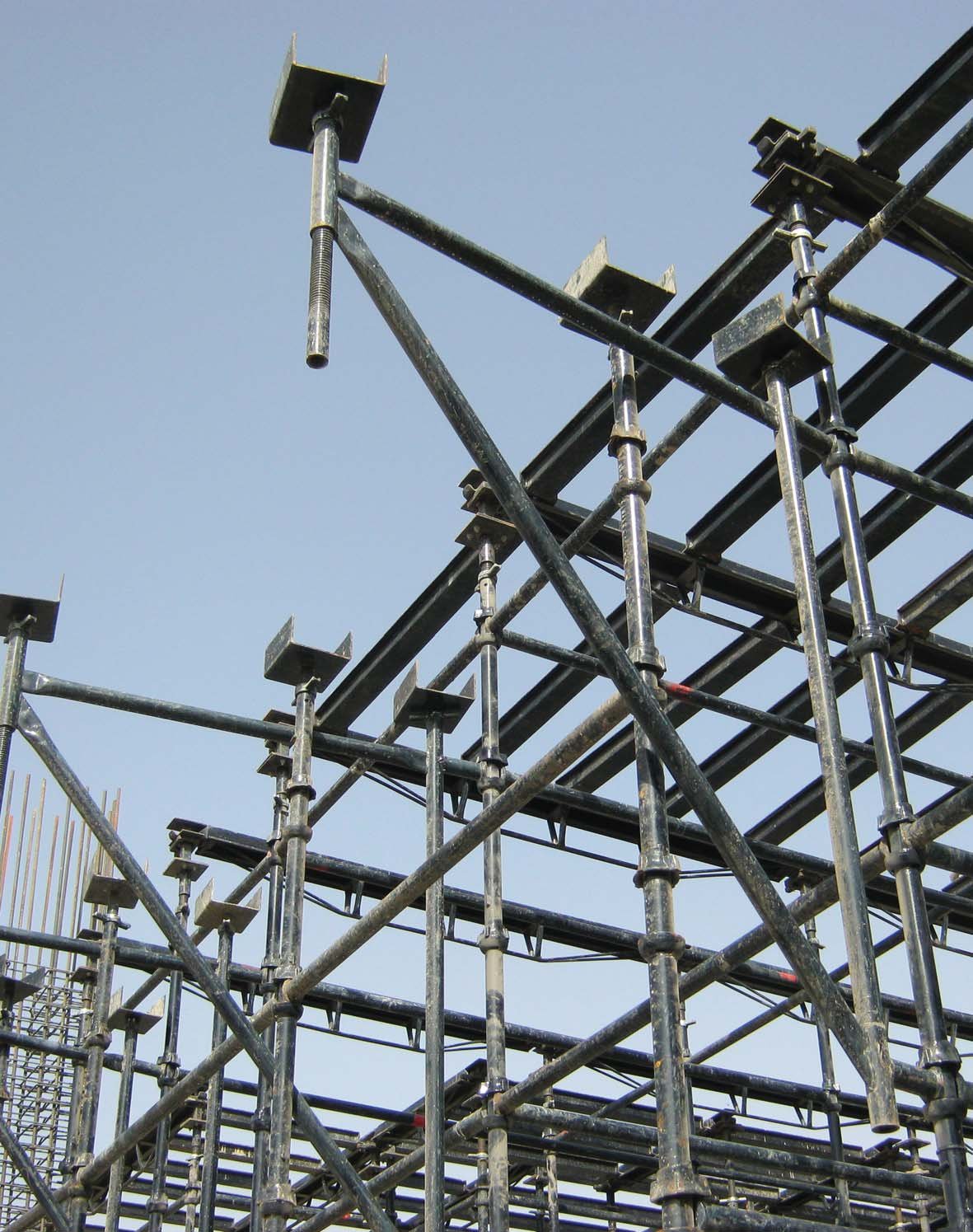
3. Jack extension. The base jack at the bottom and the U-head or universal jack at the top are the most slender parts of the assembly, and they sit outside the braced cup framework. The further they are wound out, the longer the unbraced cantilever at each end, and the lower the whole leg's capacity. This is important enough that we gave it its own article: jack extension and load capacity.
4. Eccentricity and how the load is applied. Capacity figures assume the load is applied concentrically — straight down the axis of the tube. A U-head loaded off-centre, a beam bearing on one side of the fork, or an out-of-plumb standard all introduce bending that combines with the axial load and reduces the safe value. Verticality matters: standards should be erected plumb, and a leg that's visibly leaning is not carrying its rated load.
5. Spigot joints and the bottom restraint. Standards are joined vertically with spigots, pinned where tension can occur. A well-seated, pinned spigot transmits load reliably; a poorly aligned one introduces eccentricity. At the base, a firm, level bearing under the base plate — on a sole board or concrete pad, not soft ground — is assumed by every load table.
Indicative Load vs Lift Height
The table below gives indicative safe working loads per leg for a well-braced, plumb cuplock standard with concentric load and minimal jack extension. Treat these as a feel for the trend, not as design values — published figures vary between manufacturers and with the exact configuration, and your project's governing numbers must come from the relevant load tables and an engineered design.
| Lift height | Indicative SWL per standard | Typical use |
|---|---|---|
| 1.0 m | ~65–73 kN | Heavy slab shoring |
| 1.5 m | ~55–64 kN | General shoring / falsework |
| 2.0 m | ~40–49 kN | Lighter loads / access |
| 2.5 m | ~30–40 kN | Access scaffold lifts |
The pattern is the point: doubling the lift height from 1.0m to 2.0m roughly halves the safe load. That single relationship is why heavily loaded shoring towers are built with 1.0m or 1.5m lifts, while access scaffolds carrying lighter loads can use taller lifts. For the published capacity figures of jacks and heads specifically, see our base jack & U-head load tables, and for standard and ledger dimensions, the cuplock system specifications.
From One Leg to the Whole Tower
Knowing the capacity of one standard is only the start. The applied load on each leg comes from the structure above — the weight of wet concrete, formwork, and construction live load, divided across the grid of standards. That is the other half of the calculation, and it is covered in shore load calculation for scaffolding. The design check is simply: load applied per leg must be comfortably below the safe capacity of that leg at its lift height and jack extension, with the appropriate factor of safety.
This is also why grid spacing matters. A tighter grid — for example 1.6m × 1.6m instead of 1.8m × 1.8m — puts more legs under the same slab, so each leg carries less. Reducing the grid is one of the standard ways to handle a heavier slab without exceeding the capacity of any single standard.
Codes and Factors of Safety
Scaffolding and falsework in the UAE are generally designed to recognised international standards — EN 12812 and BS 5975 for falsework, EN 12811 for working access scaffolds, with the steel itself certified to EN10219. These codes build in factors of safety against buckling and account for imperfections, out-of-plumb, and load eccentricity. The "safe working load" you read in a table already includes that margin — it is not the failure load. That margin exists precisely because real sites are never perfect, and it should never be eroded by overloading, under-bracing, or over-extending jacks.
When You Need an Engineered Design
Rules of thumb are fine for a single low-rise access lift in good conditions. But for any heavy slab, any tall or free-standing tower, any case where jacks are well extended, or anywhere the loading is eccentric or uncertain, the capacity should come from a project-specific engineered design — not a generic table. SCAFFWORKS provides in-house engineering design with site-specific drawings and load calculations for exactly these situations, alongside the manufactured standards and ledgers. If you are unsure whether your tower is within capacity, that is the safest call to make before the pour, not after.
Need a Load-Checked Scaffold Design?
SCAFFWORKS manufactures cuplock standards and ledgers and provides in-house engineering design — site-specific drawings and load calculations for shoring and access scaffolds across the UAE.
Request a Design Quote WhatsApp Us