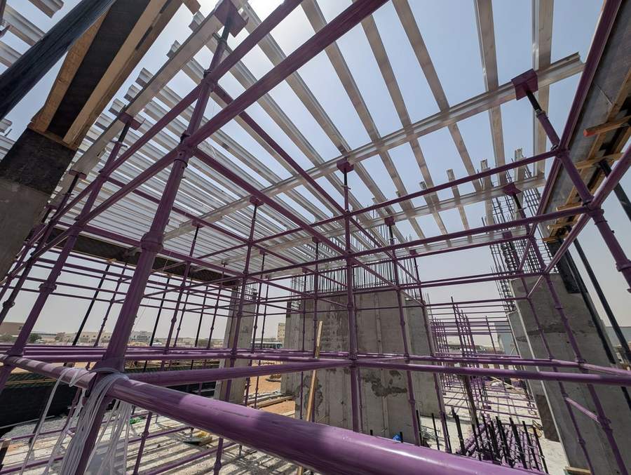
The cuplock system uses a relatively small number of core components to create an enormous range of structures — from simple single-lift access scaffolds to complex multi-storey falsework towers. Understanding what each component does, when you need it, and how it connects to the rest of the system is essential for anyone specifying, ordering, or erecting cuplock scaffolding. This guide covers every component in the system.
Standards (Verticals)
Standards are the vertical tubes that form the backbone of any cuplock structure. They're fabricated from 48.3mm outside diameter steel tube with 3.2mm wall thickness — the standard scaffold tube dimension used worldwide. What makes a cuplock standard different from a plain scaffold tube is the cups: lower cups are welded onto the tube at 500mm intervals, and a captive rotating upper cup sits above each lower cup.
The lowest bottom cup is welded at 80mm from the bottom end of the standard, and the highest bottom cup is welded at 420mm from the upper end. This positioning ensures that when standards are stacked vertically using spigots, the cup positions on adjacent standards align properly.
Standards are available in lengths from 0.5m to 3.0m, typically in 0.5m increments. The most commonly used sizes on UAE sites are 1.0m, 1.5m, 2.0m, 2.5m, and 3.0m. A 3.0m standard weighs approximately 13.9 kg, while a 1.0m standard weighs about 4.6 kg. Shorter standards are used at the top and bottom of the scaffold to achieve exact heights, and different lengths are combined to reach the required soffit level.
The stocked lengths and their weights are on our cuplock standards page.
Ledgers (Horizontals)
Ledgers are the horizontal members that connect standards together to form the scaffold grid. They're manufactured from the same 48.3mm OD × 3.2mm thick tube as the standards, with forged steel blade ends welded at both ends. The blade ends are designed with minimal projection to avoid damage during handling and storage.
To connect a ledger to a standard, you simply slide the blade ends into the lower cups on two adjacent standards and rotate the upper cups down to lock them in place. A single hammer blow on the upper cup completes the connection — no nuts, bolts, or wedges are needed.
Ledgers are available in sizes ranging from 0.3m to 3.0m. The ledger size is defined as the centre-to-centre distance between the standards it connects — not the overall physical length of the tube. The most common sizes for slab support are 0.9m, 1.2m, 1.5m, 1.8m, and 2.5m. Each node point can accept up to four ledger blade ends, meaning four horizontal members can connect to a single standard at the same level.
Ledger load capacity depends on the length. A 1.2m ledger can carry approximately 4.80 kN as a central point load, while a 2.5m ledger carries 1.71 kN central point load and 3.40 kN as a uniformly distributed load.
The eight stocked sizes and their weights are on our cuplock ledgers page.
Intermediate Transoms
Transoms span between the inner and outer ledgers (on access scaffolding) to provide mid-bay support for scaffold boards. They're made from the same 48.3mm tube but have hook-end connections rather than blade ends, allowing them to drop onto the ledgers at any position along their length rather than only at the node points.
Transoms are essential when using timber scaffold boards for working platforms, as boards have limited span capacity and need intermediate support. They're available in sizes from 0.6m to 2.5m to match different bay widths.
Spigot Connectors
Spigots are short connectors (approximately 250mm long) used to join one standard to another vertically. The spigot's outer diameter matches the inner diameter of the standard tube, so it slides into the top of one standard and the bottom of the next standard sits over it.
Both the spigots and the standards are drilled with matching holes to accept locking pins. These pins are essential when the connection needs to resist tensile forces — for example, when wind uplift could try to pull the upper standard off the lower one. On slab support falsework where loads are purely compressive, the pins provide positional security but aren't structurally critical.
Base Jacks
Base jacks provide the height-adjustable foundation for the scaffold. They consist of a flat steel base plate (typically 120mm × 120mm or 150mm × 150mm) welded to a threaded tube (38mm OD for hollow type or 36mm diameter for solid type). The threaded tube inserts into the bottom of the cuplock standard, and a nut on the thread provides height adjustment.
Base jacks are available in lengths of 65cm, 76cm, and 86cm, providing different ranges of adjustment. The base plate can be specified with or without holes — plates with holes allow the jack to be bolted to a concrete surface for additional security.
The critical point about base jacks is that their load capacity decreases as the extension increases. At minimum extension, a base jack can support the full rated load of the scaffold. At maximum extension, the capacity may be reduced by 50% or more because the unsupported length of the threaded tube increases its susceptibility to buckling.
The jack types we supply, and the allowable load against extension, are on our base jacks and U-head jacks page.
Universal Jacks
Universal jacks are similar to base jacks but without the base plate. They have the same threaded tube construction and fit into the top or bottom of the cuplock standard via a socket base adaptor. Their primary use is at the top of the scaffold, where they insert into the standard and support a drophead or forkhead assembly that carries the formwork beams.
Universal jacks can be used at both the top and bottom of the scaffold. At the bottom, they're combined with a base plate adaptor. At the top, they accept various head types. They're available in 65cm, 76cm, and 86cm lengths, with both hollow and solid options. The universal jack with socket base has a load-bearing capacity of up to 74 kN for support applications.
Adjustable U-Head Jacks
U-head jacks have a U-shaped steel plate at the top that directly supports the primary formwork beam. The U-head prevents the beam from sliding sideways during loading, which is important during concrete pours when lateral forces from the pumping operation can push beams out of position.
These jacks insert into the top of the cuplock standard and provide the same height adjustment as universal jacks. They're available in hollow and solid configurations, with the U-head dimensions matching the width of H20 timber beams, aluminum beams, or steel decking beams.
See the hollow-tube U-head jacks we supply, with weights and thread length.
Forkheads
Forkheads are alternative head attachments that sit on top of a universal jack. They provide a cradle for the primary beam — similar to the U-head but designed to be used with the universal jack rather than being a self-contained jack unit. Standard forkheads are available in various sizes to accommodate different beam profiles. Braced forkheads include additional lateral restraint to prevent the beam from rolling or displacing under load.
Dropheads
Dropheads are the key component for the early striking technique. They sit on top of the universal jack and support the primary decking beam. The drophead includes a wedge mechanism — when the wedge is struck, the beam drops approximately 115mm, allowing the decking beams and infill beams to be removed while the propping scaffold remains in place.
Dropheads connect to the universal jack via a socket base adaptor and are secured with a safety pin. They are available in versions that are separate from the socket base (requiring assembly) and versions that are pre-welded to the socket base for faster installation.
Diagonal Braces
Diagonal braces provide lateral stability to the cuplock scaffold, preventing the structure from swaying or racking under load. They're made from 48.3mm scaffold tube with swivel blade ends at both ends, allowing them to connect to the cup joints on the standards at an angle.
Braces should be fixed as close to the node point as possible, with a maximum gap of 100mm between the side of the brace and the node point. The minimum bracing requirement is one complete brace from the top to the bottom lacing level, on each row of standards, one in every six bays in each direction.
Bracing should be installed immediately after the erection of each lift to ensure that all bays are properly squared up. Removing bracing after erection — even temporarily — compromises the scaffold's stability and must never be done without engineering approval.
Cantilever Frames
Cantilever frames support cantilever edge slabs by extending outward from the scaffold. They have blade ends that fit into the cup joints and incorporate three jack locations at centres of 1.2m, 1.25m, and 1.3m from the standard centreline. Made from standard 48.3mm tube, they can be laced together if used for perimeter access. The safe working load is 10 kN per frame.
Cantilever Beam Frames
Cantilever beam frames attach to the verticals at the node points to provide support at the edge of the building for slab edge formwork and external down-stand beams. They have blade ends for cup joint connection and can accept adjustable jacks. Maximum safe working load is 10 kN.
Beam Brackets
Beam brackets support internal down-stand beams by transferring the load into the surrounding cuplock scaffold structure. They eliminate the need for full-height propping below the beam. Each bracket has two blade ends that lock into the cup joints and a horizontal extension that accepts a U-head jack supporting the beam formwork. Safe working load is 10 kN per bracket.
Scaffold Couplers
While the cuplock system minimises the need for loose couplers, they're still needed for diagonal bracing (swivel couplers) and for connecting additional tubes to the scaffold (double couplers). Swivel couplers connect two tubes at any angle and are used primarily for the diagonal braces connecting to scaffold tubes. Double couplers connect two tubes at 90 degrees and are used where additional members need to be fixed rigidly to the scaffold. Both are manufactured to BS 1139 and EN 74, with zinc plating for corrosion resistance.
Scaffold Boards and Steel Planks
For access scaffolding, working platforms are formed using timber scaffold boards (38mm × 225mm, available in lengths from 1.0m to 3.9m) or steel planks (38mm × 225mm, available from 1.0m to 4.0m). Steel planks are preferred in the UAE because they don't absorb water, don't warp in the heat, and have anti-slip stamped holes for worker safety. They comply with EN 12811 and EN 1004.
Staircase Units
Staircase units provide safe access within cuplock staircase towers. They're pre-fabricated stair flights that span between landing levels within the tower, with dimensions designed to match standard cuplock lift heights. A typical unit measures 2.05m long × 0.58m wide × 1.5m rise, with a riser height of 0.215m per step.
At SCAFFWORKS, we manufacture cuplock standards and ledgers in-house from EN10219-certified steel, and we stock the full range of accessories needed for any cuplock application. Whether you need a simple villa slab support or a complex multi-storey falsework system, we supply the complete component package with engineering design.
Need Scaffolding for Your Project?
SCAFFWORKS manufactures and rents cuplock scaffolding, formwork, and shoring systems across the UAE. Factory-direct pricing, engineering design included.
Request a Quote WhatsApp Us